Create a Super Cheap and Super Easy DIY Lavalier Microphone
A lavalier microphone is one of those small microphones that you attach to your shirt for capturing audio when a traditional mic isn’t available. It’s a “remote capture” mic of sorts. They are extremely handy to have when, say, you’re in the workshop trying to narrate your build process (just saying). The problem with them is price. Even wired ones that tether you to your camera tend to start at $99 and go sharply up and wireless variants that give you flexibility to move are far more than that.
Well, I’m about to show you a way of creating a wireless lavalier mic that costs only $10; is super easy to do; and sounds a lot better than you’d expect! As a bonus, it works with your smart phone (iPhone definitely) so it’s inherently wireless. Did I say how super easy it is to make? Super easy.
Here’s what it looks like in action:
Want to hear what it sounds like in real-world use? The following video was narrated using it:
The Hardware
The mic is made out of a set of earbuds that have an integrated microphone, like most earbuds do these days. In fact, you can use whatever set of earbuds you have on hand. I’m going to suggest a specific set, though, because of the price, the ease of modification, and the overall not-bad sound quality. It’s these ones:
They are the Panasonic RPTCM125 earbuds that are available for about $10 at Amazon
“>Amazon. Yes, you’ll be permanently altering them but at $10 how can you go wrong?
You’ll also need some sort of wire cutters (a pair of dykes pictured) and a glue gun (not yet pictured):
Making the Cuts
The handy thing about this particular set of earbuds is that each earbud has a dedicated wire going all the way down to the headphone jack. That makes a far cleaner final product.
Choose the wire that does not have the microphone on it and snip it as close to the headphone jack as possible.
Do NOT make this cut!
Yeah, that’s me just about to snip off the side with the microphone. Good thing I paused to take a picture or else I would have wasted my $10. Oops!
Cut the other wire:
That leaves you with a headphone jack hooked up to one wire that has both the microphone and one earbud. We need to get rid of the earbud. Place your wire cutters just above the microphone and snip:
Yeah, it’s safe to make these two cuts. The microphone doesn’t share any wires with either of the earbuds so all we’re doing is snipping away wires that we’re not going to use at all.
This is what it’ll look like after those cuts.
Pretty clean. If you use other headphones then it might be more obvious that you snipped off one of the wires.
Time for Glue
The microphone works as is but you’ll need to hold it to keep it relatively close to your mouth. Commercial lavalier mics have a clip that you can use to attach it to your shirt. I made my own using a binder clip that is about 3/4″ wide and fits the mic pretty well. No, it’s not anywhere near as professional looking as a commercial product but it does work.
To attach it, just heat up your glue gun and apply a dollop of molten glue to the flat part on the “bottom” of the binder (depending on which part you consider the “top” or “bottom”):
I am holding it with a third hand clamp because I needed to glue and take a picture at the same time. You can just hold the binder clip with your other hand if you don’t have that limitation. Also, you don’t need anywhere near that much glue.
The final step is to just press the back of the microphone into the glue and hold it in place for a few seconds. Within maybe 30 seconds it’ll be firmly in place!
Yeah, the construction is really that simple.
In Use
To use it, just thread the cord underneath your shirt and attach the mic somewhere on your chest or near your neck using the binder clip:
I make the recording using the Griffin iTalk app for the iPhone because, well, I have an iPhone and the iTalk allows me to sync the clips via Dropbox. Absolutely any voice recording app will work, including the default one on all smartphones. And yeah, all smartphones should work since it’s not depending on the buttons on the mic to work, just the audio.
Who cares if it’s only $10 if the sound is terrible, though, so the proof is in the pudding. Does it sound good? Yes, much better than you’d think!
But don’t take my word for it; watch the video if you want to see it in action or if you want to just hear what it sounds like, here’s a Soundcloud link:
For a point of comparison, here’s the exact same audio clip recording using a Blue Yet USB microphone (I had both microphones recording at the same time)
It’s surprising to me just how close they are! I mean, yeah, the Blue Yeti clearly has a wider dynamic range captured and is also naturally “louder” but the DIY variant doesn’t sound bad at all. In fact, since I don’t have a pop filter for the Blue Yeti, the sound on the DIY mic actually sounds mildly better on the high end since it lacks the “plosives”.
So all in all, this is a fantastic solution for only $10. Super easy to make and with much better sound than you’d expect for this price point. Win win!
I did my first miter saw upgrade by replacing the stock blade with a high quality finishing blade and then installing a third party laser.
My miter saw is a 12″ DeWalt DW715. It is overall a very nice miter saw (highly recommended) but I wanted it to be even better. This article is pretty specific to that particular saw, but the general concepts on why to do this as well as the end results will be applicable to most miter saws.
As usual, if you are a moving pictures type of person, then I have a video for you:
Note that my conclusions in the video don’t completely match the conclusions in this article because I had not yet nailed down exactly how to use the laser by the time I finished the filming.
Visually Why
The first issue is lining up where to cut. If you don’t have a laser, then the standard method is to strike your cut line on the piece and then (with the saw off!) lower the blade down so that one of the teeth is touching exactly where you want it to cut.
A blade will often have teeth that either go more to the left or more to the right. I try to pick a tooth that is aimed at the non-waste side of the board and place it so it just kisses the layout line. This cuts directly on the line.
This is a relatively quick and accurate way to line up the cuts on a flat and square piece. It becomes quite a bit harder if the piece is in any way irregular. Compound cuts on an angled piece of molding, for instance, are no fun at all using this method.
Also, having to strike a perpendicular layout line can add an addition step that can introduce its own possibility of inaccuracy.
Most miter saws come with a general purpose construction blade and the DW715 is no exception. It’s a 32 teeth GP blade and while it’s not terrible, it doesn’t cut cleanly at all.
Here it is on a piece of plywood:
Note, too, the row of lifted shards on the length of the piece:
This is very typical for a cut with a GP blade. It is almost never better than this and it can certainly be far worse.
The Upgrade Plan
Based on this, I decided I wanted to upgrade the saw in two ways. The first was to replace the blade with a “finish” blade. I chose the Freud Diablo D12100X which is a 100 tooth “ultimate finish blade”. For 12″ blades, anything above 60 teeth is considered a finish blade. I chose this blade in particular since it was a good combination of a trusted brand (Freud) and price (substantially less than some of its competitors).
The second was to add a laser. I didn’t even know that it was possible to add a third-party laser until relatively recently. The one I chose was the Oshlun LG-M01 based primarily on the reviews plus the price.
It is possible to add a second laser to the other side that should show precisely the area that the blade will cut. I’ll consider doing that in a future upgrade… maybe.
Step One: Raise the Lower Guard
The lower guard needs to be moved up and out of the way since it defaults to shrouding the blade screw entirely in its installed state. That is, you cannot access the blade screw to remove the blade until the lower guard is moved!
To do this, you must loosen (but not remove) the lower guard screw. You can find the screw by just moving the primary “upper” blade guard up and out of the way. It’s right there on the left side of the blade. It kind of looks like it could accept a flat headed screwdriver, but when I tried using one, it proved to be an odd enough size and tightly enough in there to discourage such use. Instead, the intended use is the torx head that’s on the back of the included blade wrench.
The wrench primarily has a socket head that fits the blade screw but, yeah, it’s also intended to be used on the lower guard screw. Not sure why the manual says nothing about that. The torx bit fits perfectly into the lower guard screw and it doesn’t take much effort to loosen it. A little WD-40 or similar can help persuade it, if necessary.
Here’s an important bit of (missing) information — the amount that you loosen the screw does matter!
You need to loosen it enough so that a curled flange on the guard can pass underneath it. You’ll note that if you loosen it just a little, that the guard won’t more more than a millimeter or so. That’s because that piece of the guard that is sticking up is hitting the head of the screw.
You’ll now that the screw is advanced enough if the upper blade guard rests on it when you let go. The picture shows both the upper guard resting on the screw and the lower guard’s flange passing underneath the screw head. If the upper guard still closes all the way then you haven’t loosened the screw enough.
After the screw is loosened, just push the lower guard up and out of the way. It should move reasonably easy. It’s moved enough when you can see the blade screw in the center of the blade.
Step Two: Remove the Existing Blade
The blade will spin freely normally so it won’t stay still when you try to unscrew it. That’s where the spindle lock comes into play. This is a button located on the main housing just to the right of the blade and underneath the handle.
Press that down and give the blade a spin. It will eventually “catch” and you’ll feel the spindle lock drop down a bit. That locks the blade into place. Note that it is spring loaded or something so if you let go of the spindle lock button and remove any pressure on the lock with the blade, then the lock will spring back and the blade will spin again. You can let go of the button as long as you maintain constant pressure on the lock, but it’s probably easier to just keep it pressed down with one hand.
Next up is unscrewing the blade screw using the included wrench. You will likely want to spray some lubricant on it first as it might be a bit sticky.
This part is extremely important: the screws are left-handed threads or “backwards” threads! You may have learned the old adage of “lefty-loosey; righty-tighty” or “clockwise-lockwise” or similar. Well, forget that entirely. To loosen the blade screw, you need to turn right or clockwise and essentially pretend that you are tightening it.
Left-handed threads always feel so wrong when you’re using them.
Anyway, if it’s properly lubed then it shouldn’t take too much effort to remove the screw. If it’s taking a lot of effort, then make sure you aren’t turning the wrench counter-clockwise (or anti-clockwise).
Remove the outer blade clamp and set it aside. This allows you to remove the old blade.
Note that there is a washer on the arbor. That’s because the arbor is 5/8″ but most 12″ blades have a 1″ arbor hole. The washer is a spacer to make those fit. If your replacement blade has a 1″ arbor, then just keep it there. If, however, you have a blade that has a 5/8″ hole… then just remove the washer and set it aside somewhere where you won’t forget it.
Step Three: Installing the New Blade and Laser
To install the new blade, just insert it onto the arbor from whence you removed the old blade. Simple.
If you are not installing a laser, then at this point you just replace the outer blade clamp and screw it back into place.
I did install a laser, though, so that’s next.
The laser is almost exactly the same size as the original outer blade clamp. It’s exactly the same diameter and almost exactly the same thickness.
The LG-M01 already has its three batteries installed and does come with three spares. The batteries activate when the laser is spinning rapidly, so there is no off/on switch.
Since it’s exactly the same dimensions as the outer blade clamp, we shall simply use it in place of the clamp during the reinstallation. Store the blade clamp somewhere safe.
That’s pretty much it. Make sure the writing on the laser is on the outside. You might also verify that the path of the laser isn’t being blocked by a carbide tooth… but in the case of the 100 tooth blade, that’s pretty tricky to do and so I didn’t think it was worth the effort.
Tighten the blade screw by turning it to the left or counter-clockwise or anti-clockwise. “Lefty-tighty” in this case. So so wrong feeling.
Step Three: Lower the Lower Guard
You’d think that lowering the lower blade guard back into place would be trivial and it may well be for some of you. It wasn’t for me, though. I couldn’t get enough leverage on it and for a bit, it just refused to move past a certain point. I tried various tools and all failed until I finally just grabbed the flange that sticks out with some pliers (linemen pliers) and pulled down with a pretty decent amount of force. That finally worked!
After the guard is down, just tighten the screw using the torx end of the wrench until it’s snug. It has standard thread orientation so there’s no need to think backwards.
The After Test
Now for the after tests!
First up, I strike my normal layout line and line up the blade using my normal method. Then I turn on the saw to start the laser and view where it shows up.
Basically, it hugs the layout line so closely that it’s difficult to see the line anymore. It technically cuts just to the left of the blade so it would be just to the left of the line. In practice, I found it difficult to line it up quite that precisely.
Moving on to the cut quality, though, we find this:
Wow! I’d need a zero-clearance insert to get a cleaner cut than that. And the face of the cut is actually smoother than the factory edge, even. Very impressive!
But let’s go back to the laser. One of the big advantages of using a laser is that you don’t need a full layout line nor are you restricted to flat and square pieces. A far more precise way of marking the location of a cut is to make a “triangle” mark with the point of the triangle right at the desired measure point. This is more precise because you don’t care about the width of the pencil line nor do you introduce a separate step for striking a line that bisects the measured point. If you cut right at the triangle bisection then you’re guaranteed a super precise cut.
So I did a cut on a test piece that has some funky angles and I just did the triangle method to mark the location of the cut. This cut would be difficult to do accurately using my old method. I lined up the laser just to the left of the bisection point, so that none of the laser was on the right side of the triangle.
The result is a night-and-day difference. My cut was so close to my measurement that I would likely need a micrometer to tell the difference.
Final Impressions
Upgrading the blade is a no-brainer. It did cost me $60, but it’s worth every penny of that. With a blade like that, I can make cross cuts that rival the smoothness of my table saw. Plus, doing the swap is pretty darn easy. Yes, I had a few issues as I went since the manual proved to be almost worthless, but after I figured out what to do, it was all straightforward. I can likely change out the blade in a minute or two, going forward.
The laser is a curious one in that it’s not so immediately obviously awesome. It was only after playing around with it for awhile that I discovered how useful it could really be.
See, there’s the first major drawback to all third party lasers in that they only work when the saw blade is spinning. That’s because there is one laser on the device that is pointing straight forward. It needs to spin in order to create a line. They all have internal sensors which activate only when it is spinning so that they don’t waste any battery. I’m not a huge fan of having to start up the saw just to make the final adjustments for the positioning of my piece, though! I’m going to think about my possibilities of maybe adding some kind of external switch to the outside of the device that will allow me to turn it on even when the blade is still.
My original tests (and those that I talk about in the video) were all at least a little disappointing since they didn’t increase my precision or accuracy over the manual method of lining up the cut. This was because I was using the less-accurate way of marking the cut line, though. It was a revelation when I switched to using the triangle style method! Now I’m finding that my precision is approaching table saw levels. That’s pretty darn impressive.
I’ve mentioned my table saw twice so far and said that this upgrade makes the miter saw competitive. The table saw does still have to big advantages. One is that it has a zero clearance insert that allows for completely chip free cuts. My miter saw with the new blade comes close to that, but not exactly. Well, one of my future plans is to make a miter saw station that will include a removable zero clearance insert. I suspect that I’ll have identical cuts after that.
The second advantage of the table saw is with repeatable cuts. That is, when using a fence or using a stop block on a cross cutting sled, I can cut piece after piece that are perfectly identical in size. No amount of measurement will get you that same repeatability. That’s where my future miter saw station comes into play. That will have an integrated ruler and stop block system that will get me my repeatable cuts.
One final advantage of using a crosscut sled on a table saw is that I can visually see just how wide my cut is going to be, based on the zero clearance opening on the sled. With my laser, I only have one side marked. It turns out that if I care enough that I could do something about that. It’s possible to get a laser made for a radial arm saw that is slightly thinner and install it on the right side of the blade. This would give me a laser line on both sides of the blade that are separated exactly by the blade kerf. It would also allow me to place my finished side on either side of the blade instead of always on the left, as with my current laser. I’ll consider doing that.
But for $25, that laser is already worth the money for what it does as-is.
All told, this was an $85 upgrade and I could scarcely be happier with the results.
I find myself lifting heavy sheet goods on a regular basis and I nearly always do it on my own. When you consider that a full 4×8 sheet of drywall or plywood typically is in the 50lb to 70lb range and a full sheet of 3/4″ MDF weighs a whopping 85lbs, then the need for some tools to help out became self evident.
I have three such panel carriers, each with their own unique strengths and weaknesses. So which panel carrier is best?
The Budget Pick: Stanley Panel Carry
The Stanley Panel Carry is the budget pick and is typically the one most used by the pros. It is ubiquitous and available darn near everywhere.
You usually see it in orange or yellow; mine is in green. It retails for between $7 and $10, typically.
Using It
To use it, you lift the panel up somehow and place it on the Stanley’s “hook” roughly in the center of the panel.
Then, crouch down and grasp the handle with your dominant hand. Stabilize the top of the panel with your other hand. Lift up the panel using your legs and not your back. Carry it to wherever it needs to go.
Strengths
The Stanley’s biggest advantage is its price, since it’s a fraction of the cost of the other two options.
The angled handle also allows you to grasp it with your hand and wrist at a natural angle. This is far easier on your wrists than carrying a panel without a carrier. No comparison at all!
The weight is relatively uniformly distributed along your body (with one notable exception). It’s much more manageable than using nothing.
The panel position allows you to raise and lower the panel while you are carrying it. This gives you the opportunity to climb over sills or thresholds or the like, since the panel is already a foot or so off the floor and you can raise it even higher.
And finally, the panel is relatively easy to maneuver while carrying.
Weaknesses
The “somehow” in placing the panel on the Stanley is a chicken and egg problem. You need to lift the panel to get it on the Stanley but the Stanley is what you lift it with. I typically just grasp one side of the panel and use a corner as a pivot point to lever it up. This gives me some room to slide the Stanley under it. This does have the very big disadvantage of possibly chewing up that corner since you have a lot of weight riding on it. In particular, I find that I have to always cut away that corner if it’s MDF since it’s nearly always rounded or flattened.
The weight is mostly evenly distributed but the one notable exception is that quite a lot of the weight is born by front of your palm. Unless you have a very muscular hand, it’ll get tired decently quickly. Wearing gloves helps quite a bit and it’s still better than the awkward angle that your hand is wrist is at without a carrier, but yes, your hand will be very sore at the end of the day.
Using this carrier does not make the panel lighter. You still feel every pound of it. It’s easier to handle, not lighter.
It’s hard to see where you are going unless you are extremely tall. I’m 6′ and I can’t see over a 4×8 panel, meaning that the view to my right is completely blocked off. Yes, I’ve run into many things that way.
Finally, the Stanley is made of plastic, which gives it a cheap feel. It is inexpensive, so that makes sense.
The Quick Picker Upper: Gorilla Gripper
The Gorilla Gripper clamps on to the top of a panel and uses the panel’s own weight to tighten the clamping pressure. The more the panel weighs, the tighter it grips. It’s not unlike one of those old-school Chinese finger traps in that respect.
The Gripper goes for about $50 and I’ve only found it online.
It is very solidly built out of aluminum with grippy pads in the clamping part. The clamping is done entirely via leverage. Here it is “loose”:
Using It
To use it, you place it over the top of a panel with one pad on each side. Then pull up on the handle. This upward pressure uses the levers inherent in the design to tightly clamp down on the panel.
Release the pressure on the handle and the clamp loosens. I’ve heard some reports of a panel slipping in use but I don’t see how that would be possible. This design holds on very tightly as long as you are carrying the weight.
To lift the panel, crouch down and hold your arm close to your body with your hand and palm facing up. Reach up and grasp the nicely padded handle. Finally, lift up with your legs. The panel is now lifted to shoulder height.
Strengths
This is the only panel carrier that solves the chicken and egg problem. You simply walk up to the panel and pick it up with no fuss and no extra steps. It is by far its biggest advantage.
The visibility is very good since the panel can only go up to shoulder height. You can see all around you while carrying the panel.
The handle is very comfortable (much much more so than the Stanley) since it’s so thickly padded and the Gripper as a whole is very solidly built.
The weight is distributed along your arm and doesn’t put any extra stress on your hand, like the Stanley does.
It is just as easy to maneuver as the Stanley.
Weaknesses
Since it only lifts the panel to shoulder height, you need to be relatively tall to use it with 4×8 sheets. That is, measure your shoulder down to the floor and if it’s less than 4 feet, then you can’t use this. You might be able to lift the panel higher if you’re a weight lifter, but I cannot at all.
The weight is almost exclusively born by just your arm. In particular it feels like you are doing bicep curls while using it. Since it’s not as distributed as the Stanley, the panel does feel notably heavier over time than with the Stanley. This is because just your arm will get tired faster than your arm plus torso will.
It’s difficult to walk over obstacles since you cannot raise and lower the panel while carrying it. Measure your shoulder to the floor and subtract 4 feet and whatever is left over is how high an obstacle you can walk over while using the Gripper. My shoulder is roughly 5 feet up so I have no more than a foot of height to play with.
The Long Distance Option: Panel Panel
The Panel Pal is the only one of the three that has wheels on it and so is the only one that will actually offload some of the weight for you.
It retails for $50-$60 and is available exclusively online.
It is made almost entirely out of plastic.
Using It
Pick up the panel somehow and place it on the rubber padded part of the Panel Pal. I find that putting it near the center of the sheet offloads the most weight, but makes it harder to maneuver. Putting it 3/4 along the length of the panel seems to be the best compromise of weight distribution and maneuverability.
Once in place, just pick up the unsupported end (it’s now far lighter than the whole) and push it to where it needs to go:
Strengths
It has wheels, so it offloads the majority of the weight of the panel. Neither of the other two make the panel any lighter. This one does. If you have a lot of sheets to carry a long distance, then this is the only one that will not significantly tire you out over time.
Since it supports the weight, you can sometimes carry more than one at a time. I found that having a helper makes this a lot easier, if the helper supports the front of the panels.
It’s far less expensive than it’s normal competition. Most wheeled panel carriers are in the $250 to $300 range and up!
Weaknesses
The panel is not clamped into place. As a result, the panels like to shift around on the Panel Pal, which can make steering it harder than you’d think.
The center of gravity is high on the panels and since they are not clamped in place, they have a tendency to want to tip over. More energy is spent keeping them upright then from supporting or pushing them.
Basically, a carrier with four wheels and a clamping mechanism would be far easier to support and steer than the Panel Pal is.
The wheels are small so even tiny bumps or thresholds will be too much for it. It’ll get over gravel or grass or any smooth surface, but that’s about it. Forget about rolling into into a house over a door threshold.
The Panel Pal is made of plastic, which gives it a somewhat cheap feel. Considering it is the most expensive carrier in this list, you might expect it to be at least as solidly built as the Gorilla Gripper. It’s not. All of the metal wheeled panel carriers are far more expensive, though.
Which Panel Carrier Is Best?
Honestly, I recommend buying all three if you carry a lot of heavy sheet goods.
The Panel Pal is great for long distances but is no good at any threshold. It stops cold at any doorway. It also has the “chicken and egg” problem in that you have to get the panel on the Panel Pal in the first place. All that said, when I was carrying dozens of sheets of drywall a good 100 feet or more, I found the Panel Pal to be absolutely invaluable!
The Gorilla Gripper is the only “pick up the panel and go” option and is by far the easiest to use. There’s just no messing around. Clamp and lift. But you do need to be taller to use it and it makes the panel “feel heavier” more than the other two. I wouldn’t want to use this for multiple panels. Also, thresholds can be a problem if they are high due to the shoulder height restriction.
The Stanley Panel Carry is versatile and inexpensive but don’t underestimate how much weight is loaded down on the front of your palm. That gets very uncomfortable very fast. I can carry more panels than with the Gripper, but am more selectively sore afterwards. Also, getting the panel onto the Stanley is a pain. You can’t beat it for carrying a piece of drywall over a window sill, though.
So I end up using all three of them. Here’s my procedure:
I approach the panel with the Gorilla Gripper. I pick it up (trivially) and place it down on the Panel Pal. I hook the Stanley on top of the panel (upside down) and push the panel to roughly where it needs to go using the Panel Pal. After I arrive, I take the Stanley and since the bottom of the panel is already raised up, I just hook it under that and carry it to the final destination. It works very well.
Seriously, Break It Down
If you are tall enough; won’t be carrying too many panels at once; and don’t mind the price, then the Gorilla Gripper is hard to beat.
If you are shorter; don’t want to spend the money; or will be carrying the panel over a higher threshold, then the Stanley Panel Carry is the obvious choice.
The Panel Pal is only justified if you are carrying a lot of panels over a long distance. Get the Stanley with it to go that final bit over the threshold.
This is the first Granworks Guide — a hopefully recurring series covering how to do specific tasks, with all the essentials covered. This guide is all about taking a rusted and dull shovel and breathing life back into it. The first part talks about how to remove the rust and the second part shows how to sharpen it.
As an example of just how much it’s possible to rejuvenate a shovel, witness the before and after of an earlier shovel:
Pretty dramatic.
Update: Viral?
Okay, this is a little bizarre. Apparently this topic hit some kind of nerve since an imgur album and reddit post went (relatively) viral and the video has received quite a few hits.
First, the imgur album has over 600,000 views as I write this; was on the list of most viral posts for the day; and garnered me a “trophy” from the imgur team for an excellent submission. Huh.
Then, the reddit r/diy post was at the top of reddit for most of the day; has over 5400 upvotes; and has over 1100 comments. Yeesh.
But then apparently Popular Mechanics picked it up and wrote up their own article based on the video and linked to it.
All that caused the Granworks YouTube channel to double the amount of subscribers and increase the view count to between 3x and 10x our normal. It’s at 6800 views right now, with actual comments and everything.
Very surreal day.
Video
The video may make more sense than a blog post since the actions and motions matter quite a bit.
Why Sharpen?
It’s fair to ask the question “why sharpen a shovel in the first place?” After all, they typically aren’t sharpened when you buy them from a store. Well, the reason why is because using the shovel is far easier when the blade is sharp. It’s hard to describe just how much easier when you’ve never used a sharp shovel before. In general, it just take a lot less effort to drive the sharp shovel into the ground and goes deeper with each thrust.
The original sharpening can also be done in a matter of a few minutes and thereafter you can touch up the edge in less than a minute. It’s a small amount of effort for a big payoff.
Remove Rust
Shovels need to glide smoothly to work effectively and rust really gets in the way. It will also destroy the shovel if not taken care of soon enough.
There are a number of ways to clean rust off of a tool, including some chemical methods. I’m going to cover two physical methods — sandpaper and wire brushes.
Sanding Away the Rust
The majority of rust tends to be on the surface of the metal and so using sandpaper can be reasonably effective. The grit does appear to matter. If the rust is very thick and coarse, then 100 grit or 80 grit works the best. If it’s fine rust, though, then those coarse grits work surprisingly poorly. I found 220 grit and 320 grit to work far better in those cases.
You can sand using a bare piece of sandpaper. That works well with curves and recessed areas. I don’t recommend it for large areas, though.
A better option for flatter areas is a sanding block. In this case, the fine grained rust was sloughed off relatively easily with the sanding block.
If you have a random orbit sander, then all the better.
This has the same issue as the sanding block in that it won’t get into recessed areas, but it does do an admirable job of removing a lot of rust fairly quickly.
Note that all of the sandpaper options fail at getting rust that is embedded below the surface. You can see some examples of embedded rust in the low right hand corner of the above pictures. No amount of sanding gets to that rust, save sanding away an entire layer of metal (not recommended).
Grinding Away the Rust
A faster and more complete option is to use an angle grinder with a wire cup brush.
There are two main kinds of wire cup brushes. The first kind has a bunch of individual independent wires and is intended for fine work. Those have a tendency to lose wire bristles, though, and so aren’t often recommended. I use the twisted wire type. Those are far more aggressive but do have the benefit of staying together for much much longer.
It’s possible to get wire cup brushes for drills. Those would work similarly to the angler grinder variants, albeit quite a bit slower. That’s because drills (especially cordless ones) don’t operate at anywhere near the speed that a grinder does.
The wire cup brush not only works faster than sanding but it also can tackle the embedded rust. It doesn’t take long at all to almost completely remove the rust from even a heavily rusted shovel.
It’s worth noting that it won’t get all of the rust. The brush can’t reach all recessed areas and isn’t great around edges. I do tend to follow up after the angle grinder with some loose pieces of sandpaper to get some of the hard to reach areas as well as to smooth away the main surfaces.
Here’s what the shovel looks like after the rust has been removed.
Sharpen Using a Metal File
It’s entirely possible to sharpen the shovel by hand using a metal file. It doesn’t take as long as you might think, either. All you need is a “bastard” file or any metal file that’s not coarse. A bastard file just refers to a metal file that is not fine and not coarse. Here’s an example:
Note that metal files almost always have their teeth pointing forward. You can feel the difference by running your finger over the file. You can even see them if you look closely at an angle. This matters because that means that they are intended to be pushed forward and not pulled backwards. In particular, never saw a file back and forth. This will dull the teeth. Always push the file forward or “draw” it along an edge.
I secure the shovel using a vise so that the shovel is at a slight angle. The idea is to then grind a flat edge on the front of the shovel that is roughly parallel to the floor. Since the shovel is at an angle, this flat area will create a bevel. The actual angle doesn’t matter, as long as there is some bevel.
Hold the file with your hands on both the front and back of it. Push the file forward roughly parallel to the floor. You’ll find that it “cuts” into the much softer shovel metal relatively easily. I tend to move the file to the side an inch or two while I make the forward stroke.
At some point I also make a wider sweeping stroke that covers the entire sharpened area at once. This is called a draw stroke
This method can be exclusively used to sharpen a shovel and should take only a few minutes the very first time. Each time after that to just touch up the bevel takes less than a minute.
Sharpen Using an Angle Grinder
Still, it’s faster yet to use an angle grinder with a metal grinding wheel to make the original rough bevel. I use a 1/4″ metal grinding disc.
These are used by welders to grind a mounded weld flush. That is, it can remove a lot of metal in a hurry. The soft edge of a shovel is no challenge at all for it.
In fact, it can work so quickly that you need to be a little bit careful. If you don’t pay attention to your progress, then you might find yourself removing far more material than you intended. Also, if you spend too long in one spot, you can cause the metal to heat up too quickly and that will “detemper” the steel, significantly weakening it.
So make light and quick strokes. That’s all that’s needed.
Similar to the metal file, just keep the grinding wheel roughly parallel to the ground. This will form the bevel extremely quickly — much much faster than the file does.
It does create a relatively rough cut, though. You can visibly see circular marks in the bevel from the cutting motion of the grinding wheel. As such, I always follow up the rough cutting with the grinder with a few draw stroke passes using the metal file. That smooths it out.
At this point, the shovel should feel notably sharp to the fingers and will actually cut you if you aren’t careful. You don’t want it to be knife-sharp or anything like that, but it will be sharp enough to make some damage.
Future Protection
The shovel is still susceptible to moisture at this point and risks getting rusty again. Now is a good time to apply a protective coating. It’s commonly recommended to use boiled linseed oil for this task, but I have never had any on hand and so I haven’t tried it. Instead, I use a Rustoleum Rust Inhabiter spray which you just spray on and then wipe off the excess. It lasts for quite a while, in my personal experience.
Here’s what this shovel looks like after a coating.
Final Thoughts
It takes me maybe 10 minutes to bring a completely rusty and dull shovel to a largely rust-free and sharp shovel. That’s well worth the time considering how much easier it is to use the shovel afterwards. I really can’t stress that enough.
After the initial rejuvenation, I just make sure to brush off all of the dirt after each use and then every so often touch it up with a metal file and some more rust inhabiter. That takes less than a minute.
This post is a continuation of the two part series on building columns for our home theater. It covers making “black mirrors”, creating doors with inset mirrors, installing 35mm/euro hinges, building fabric frames, and installing the columns. See part one for everything else.
Making Mirrors
One of the planned standout aesthetic features of the columns was going to be “black mirrors” on the doors. You’ll see what I mean in a bit.
The mirrors needed to each be 11″ x 20″ so I started with a sheet of 1/8″ plate glass from HD with a size of 16″ x 20″. That meant that I only needed to make one cut each. I have a video on cutting glass in this post:
That’s a generic video, though, and this is specific to the columns. I started with the necessary tools which is pretty much just a glass cutting wheel, a straightedge, a Sharpie, and a tape measure. Oh, and the glass.
I used a drywall T-square just because that’s what I had on hand. I used a Sharpie since I have terrible luck with wax pencils. I started by making a mark at 10-7/8″ to account for the width of the cutting tool from the edge to the center of the wheel. I believe it’s actually 3/32″, but I don’t need anywhere close to 1/32″ accuracy in this cut:
Next up is scoring the glass with the cutting wheel. This is pretty easy — just press down with moderate pressure and make one smooth pass along the straightedge. It makes a “crunching” sound while making the score line.
Said scored line looks like this up close. It looks exactly like a scratch on the glass and not at all like a crack.
Next step is putting a fulcrum of some sort underneath the scored line. I used a dowel since I had one handy.
And final step is to put on some gloves and apply steady pressure on the glass on both sides of the fulcrum. It snaps very easily and has a perfectly straight edge.
Apparently it’s razor sharp, too, as I got multiple “phantom” cuts (didn’t know about them until they bled) while handling the glass without gloves. I just switched to using gloves.
At this stage, I have a pane of glass that’s the right size, but it’s not a mirror. To turn it into a mirror, I simply need to paint the back of the glass black.
I had some flat black latex paint out from painting a different part and so I decided to try using that paint instead of spray paint, as a lark. Did it work? Nope! It was a complete and utter disaster!
Yeah, it had some reflective properties, but it was massively streaked and it peeled off at even the lightest touch. Lesson learned: latex paint does not stick to glass.
I actually already knew that very well so I’m not sure why that didn’t pass my mind this time around. Oh well.
I fixed the mirror by spraying it with Rustoleum acrylic paint, which is what I used in the past. It doesn’t matter if it’s high gloss or low gloss. It works perfectly:
You can see what I mean by “black mirror”. It’s definitely a mirror since it’s very reflective, but it gives everything a deep black feel at the same time. I love the look of those.
Making Doors
I wanted the doors to be 3/4″ thick but also wanted my mirrors to be inset. My first attempt was to route out that space using a custom built long router base (will be doing a video on that in the not too distant future) and a jig. That sort of worked, but it was a massive pain and took far too long and generated far too much dust to be worth it. So I fell back to plan B, which is to use 1/2″ MDF as the base of the door and build a frame around the mirror out of 1/4″ hardboard. The combined thickness is 3/4″ and the mirror is inset.
I started by gluing some 2″ wide hardboard strips to a potential door:
But quickly realized that it would take too long to do it that way and so future hardboard pieces were glued but then tacked in place using 3/8″ staples. No photos but that is in the video.
The doors were painted black to make up for any tiny gaps between the mirror and the white hardboard frame. The door was originally planned to be 24″ and so would have a 20″ mirror and then two 2″ pieces on top and bottom. I realized after the prototype, though, that that’s too long for three of the column locations and so I changed the design on the spot to be 23-1/2″. That meant that the bottom piece was reduced to 1-1/2″. I attached the top and bottom hardboard pieces with the mirror held temporarily in place to ensure that I got a good fit:
All staple holes were filled; it was primed; and them painted white. The mirror is attached using hot glue:
My thinking was that using hot glue makes a relatively strong connection but not necessarily a permanent one. Therefore, if the mirror ever breaks then I can possibly pop it out of the door and replace it without having to replace the entire door. I’d definitely have to replace it if I used something like construction adhesive.
Installing the mirror was as simple as pressing it into place:
Euro Hinges
I’ve always wanted to try my hand at installing 35mm or “euro” hinges but never had a good excuse. Well, I made sure to make an excuse by deciding to hang my doors using euro hinges! I bought a 35mm Forstner bit and a set of full overlay hinges. The hinges came with paper templates to layout the holes, but those are entirely inadequate. That’s because it’s very important to have exact placement of the holes and paper templates are essentially unusable after the first set of hinges. So I made some jigs using the paper templates:
The templates have a “fence” on them that registers with the edge of the board and then a center line that lines up with a line on the board. The two of those make for very precise hole locations time after time.
I started by striking a line between the door and the column to make sure the two pieces match up. Euro hinges are well know for adjustments but you might as well start out with everything correct to minimize having to adjust.
Then I used one of the templates to guide the Forstner bit on my drill press to the right location. My procedure was to use the template as a guide and press the pointed part of the bit into the door. I then removed the template and used the pressed in point to center the bit as I drilled to the proper depth.
The template has guides for the pilot holes for the screws, but I found it easier to use the actual hinges in this case. I have a self centering drill bit that is made specifically for hinge screws and so I just put the hinge in place and used that bit to create the pilot holes. Simple!
I did use the guides on the other template to locate the pilot holes for the hinge part that’s on the column.
I don’t have any photos or even video of actually hanging the door. Weird.
Fabric Frames
I made the frames for the acoustically transparent fabric frame part out of some scrap primed popular that I had laying around. I just cut out the sizes I needed from the scrap and spray painted it black using the same paint I used for the mirrors. That was far quicker than painting them by hand.
Next up is measuring off some fabric to cover the frame. I am using the same Scott landscaping fabric that I used elsewhere in the MVP version of the theater.
The fabric easy to work with, works pretty well acoustically, and is pretty cheap… but it is also extremely flammable. Worse, it melts when it burns and emits a nasty smoke and odor. So yeah, I’m eventually going to replace it with some proper fabric like GOM. I’ll likely replace the entire frame when that time comes.
I marked out the size needed using chalk and then cut using scissors. It cuts very very easily.
The fabric is attached to the frame using upholstery staples driven by my upholstery gun. I didn’t spend an inordinate amount of time trying to keep it flat since it’s just temporary.
Pictures of the completed frame can be found floating around in later photos.
Column Hanging
The columns are hung on the wall using two plywood cleats. For three of the four cleats, I attached them to the back of the column (one near the top, one just under the shelf) using pocket screws. The other column has it’s own section, as you will soon see.
You can see one of the fabric frames chilling out in the background of the above picture.
I found the stud using a combination of a magnet and my laser level. I actually have all of this info in my SketchUp model but it was quicker to use this method this time.
Each column is raised up to to the soffit and give itself around 1/2″ of clearance from the riser. I didn’t want the columns touching the riser in any way since the riser is decoupled from the walls and resting the columns on them would effectively recouple them.
The columns are attached to the wall using a pair of 3″ screws driven though the cleats and directly into a stud. They are there pretty solidly.
And here’s what it looks like fully installed and with the fabric frame in place.
The frames were sized to fit pretty tightly in the face frame, since I was planning on using just a friction fit at this point. Maybe when I remake the frames I’ll make them with stiffer material and so will want to use magnets or similar… but for now, there’s no connection method other than friction keeping them in place.
Custom Cuts
One particular column stands out as being a notable pain. See, there is one spot in the back of the theater where the riser is connected to the rest of the world. Specifically there is a conduit that runs from the equipment closet into the attic and then down into the riser. That vertical conduit meant that I had to cut custom holes in my column shelves to accommodate it since, well, it’s a permanently installed conduit.
I measured out the placement and width and cut as much as I could with a jigsaw. I didn’t have enough space to make the curve so that was done using a spade bit.
I did that in the theater since I didn’t trust making the cuts beforehand. In retrospect, I probably should have done it in advance since it would have been far easier.
But wait, there’s more!
I totally forgot about the second connection into the riser. There is a flexible conduit running from the electrical outlet that will be hidden by the column that goes into the riser. This is also permanent and so I needed a hole in the bottom shelf that handled both the vertical solid conduit and the smaller flexible conduit. I didn’t realize that until I had already moved the column into position. Talk about having to work in cramped spaces and generating tons of sawdust in an area where you really shouldn’t have any!
The video shows better how awkward working on this was.
Done
And here’s what they look like completely installed!
All in all I can say that I’m reasonably happy with the end result. I definitely like the look from a distance. I’m also going to keep replicating that theme of a 30 degree angle plus those colors. But if I did this all over again, I probably wouldn’t use hinges on the doors. They do make them stick out more than I’d like. Magnets would make more sense. Also, doing the painting piece-by-piece was far more of a pain than was justified. Future columns would definitely be primed once after construction and then painted once after that.
Maybe the mirrors aren’t worth it, either? You can’t even see that they are mirrors from most angles. Heck, you can’t see the mirrors at ALL for the two back columns and can only see that the front two have mirrors when sitting down in the front row and looking to the side. Yeah, not worth it. Maybe I can use that concept somewhere else in the theater, though. We’ll see.
I’m building a home theater and have been doing so for the past year or two. At the time of this post, it’s in an “MVP” stage meaning “Minimally Viable Product”. That is, we can watch movies in there and they look and sound great… but the room is far from done. This is the first granworks post on the theater and it’s all about moving past MVP.
This is all about creating the four columns for the theater. They will eventually hold the surround speakers (when I create them) but for now they are there for some storage and mostly for aesthetics. Notably, these are the first theater pieces that will strongly influence the final style of the theater. Until now, everything has been either black or grey and plain.
Without further ado, here’s the build.
Video
Yep, all theater build steps going forward should have an associated video. Here’s the very first granworks video about the theater:
It’s 16min which is a bit on the long side, but it is condensed massively from the nearly two hours of video footage I shot!
Cutting to Size
The columns are built almost entirely out of 3/4″ MDF. I don’t have a truck so I end up renting a U-Haul trailer and buying a bunch of sheets at a time.
I need MDF to build my speakers and subs in the future, so those will definitely come in handy. I only needed one 3/4″ sheet for the columns (and part of a 1/2″ sheet, to be discussed later). Each sheet weighs upwards of 85lbs so I try to break them down into more manageable sizes using my circular saw while the panel is on a sheet of foam insulation on the garage floor:
I did one cross cut to rough height and then one rip cut to make sure that no piece was more than about 2-1/2′ wide. That’s far more manageable!
After that, it was easy enough to cut out the 2″ wide face frame pieces:
And then the 8-1/2″ wide column side pieces:
As much as possible I tried to cut all of the same pieces at the same time so that they would be precisely identical. When that wasn’t possible I’d at least cut paired pieces together to make sure that they were at least the exact same size. For instance, I couldn’t use a stop block to cut the pieces to length since they were too long, so I made sure that I ganged up both pieces for each individual column together to ensure that the columns wouldn’t have one side shorter than the other:
Working the Angles
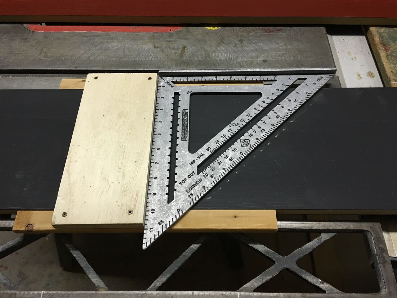
The columns have an angled top piece which is either 30, 60, 120, or 150 degrees depending on your point of view. Quite a few pieces needed to be at the right angle. Those pieces included all of the face frame side pieces; the face frame top piece; and the top cap. Since they were going to be meeting up, I decided to cut all of them at the same time using the exact same saw setup.
So the table saw is set to 30 degrees:
Then all six face frame side pieces (three columns since I already built the prototype) are ganged together so that they are all cut at once:
I’m not sure why I didn’t use a table saw insert here since having a wide gap like that is pretty dangerous. Oops.
Then I cut the 1-1/2″ face frame top pieces as well as the top caps at the same time. I used the same piece of MDF to ensure that the angles were complementary:
The angle on the side pieces was quite a bit harder to do. My original plan to cut them on the miter saw was out since that angle was 60 degrees from the saw’s point of view and it only goes to 50 degrees. I attempted to use the miter saw no matter what by just rotating the piece to be perpendicular to the saw fence:
That didn’t work very well at all since being even a tiny amount off resulted in a cut that was also off by quite a bit. So I cut the rest of them using the miter gauge on the table saw. I was able to get at least one of them to be precise and the rest were done purposefully a tiny bit wide. That allowed me to use my flush trim bit to make all of the rest of the pieces be exact.
Face Frames
It’s pretty traditional to build face frames using pocket screws to speed up the process and since I’ve had decent luck with that method in the past, I figured I’d use them here.
I usually build face frames with poplar, though, and have never made them with MDF before. I had an outstanding question on whether or not the pocket screws would cause the frame to split. Well, that question was answered definitively and in the affirmative:
Erg. That required quite a bit of sanding and putty to make it presentable. After that, I made sure to create the rest of the face frames using only glue and clamps. It takes longer, but at least it works!
Not Finished
As an aside, it was at this point that I measured my face frame and noted that it was only 14-7/8″ wide instead of the intended 15″ wide.
What!? I did some checking and it turned out that my table saw guide was off by a tiny bit and that tiny bit added up over multiple pieces. I’m guessing it was off because it was originally set for a full-kerf saw blade and I since switched to a thin-kerf blade. Maybe? I fixed it but was really glad that I did all of my cutting in batches beforehand. Even if they weren’t precise, they were at least all the same.
It was around this time that I did some dry fits of my angled top cap and discovered another mistake. Specifically, a mistake with the face frame that I put together with pocket screws.
See, here’s my face frame with the “good” side forward and the angle on the top:
Oh, that ain’t right!
What if I flip the piece around and have the “back” side in front?
Yep, it turns out that I messed up the front and back for my face frame. I was faced with the choice of either re-doing the frame entirely or fixing it in place by filling in the pocket screw holes. I figured that the putty route is likely the fastest and so did that. Thankfully, it did work (no pictures). Whew.
So Much Paint
And now we start to paint. Oh, so much painting. So so much painting! I took somewhere close to two hours of video for the build and maybe 45 minutes of it was painting… and I stopped filming the painting parts at some point. Yeah, this was one of the biggest reasons that the build took almost three weeks!
See, I decided that I wanted to paint each piece individually before assembly AND to make sure they were all primed, first. This meant repainting each piece multiple times and because there are multiple types of paint, I had to do a lot of waiting in between for them to dry.
There were four types of paints that I had to deal with. The first was the shellac based primer Zinsser BIN, which is alcohol based. That required either denatured alcohol or ammonia for cleanup and since it dries incredibly fast, you had to cleanup in a hurry. It’s pretty amazing stuff, though, so I’m going to have future posts and videos on using it with MDF.
Next up was the white and black paint for the frame and interior, respectively. Both were latex based so cleanup was simple but as they were two diametrically different colors, I did need to ensure that I used different brushes which slowed things down.
Finally, there is the red color which is a oil based gel stain (Old Masters Crimson Fire). I absolutely love the final results of this stain since you likely cannot get anywhere near that depth of color with a water based paint and yeah, it spreads very well. But since it’s oil based, cleanup is an unholy pain, involving multiple pails of very stinky mineral spirits or paint thinner. Cleaning oil paint or stain brushes is one of my least favorite things to do.
But like I said, you can’t get that color any other way and it does look fantastic. I wouldn’t have used red at all if I couldn’t get that kind of red.
Dados
I routed out dados for the column shelves — which are mostly there to define the bottom storage box and to also provide structure to the column. I already covered this in a previous post (with video) and so rather than completely re-iterate it, here’s a link:
I established the initial width of the columns using physical pieces. This was mostly the top caps, since they were handy. I just clamped them on ensuring that the edges were perfectly flush and from that I was able to make accurate measurements of the necessary shelf sizes.
But before attaching the shelves, I first attached the top cap to each column. Since it’s on an angle, there was no easy way to clamp it. Therefore, I just applied some glue and then used brad nails to secure it in place:
Next , I cut the shelves to width and install them into the dados. Those were done using only glue and some clamps. I made sure that they were square at this stage since fixing them later would have been quite a pain
Finally, I attached the face frames. I was originally just going to use glue and clamps but I only have enough clamps for one at a time and didn’t want to wait — so I used brad nails on the frames, as well.
That picture shows a glaring procedural error on my part. See, brad nails always have a wedge on them rather than a true point and that wedge wants to follow grain. The practical result is that brad nails will nearly always deflect perpendicular to the nail gun, if they are going to move at all. That’s very bad if you’re nailing along a narrow edge because a blown out nail will very likely do so on your “good” side. That’s why it’s always important to orient the nail gun perpendicular to any long edge rather than parallel to it.
What do you see in the picture? Yep, I’m nailing parallel to the long edge. And yeah, I had two blowouts doing this and both blowouts were on the “good” side (no pictures). Erg. I had to spend much more time than I wanted fixing and then minimizing the results of the blowouts. Lesson learned — always nail perpendicular to an edge!
End of Part 1
I split this post into two parts since it’s getting excessively long. Part two covers creating the doors and the fabric frame, plus installation.
Creating dados for shelves is a pretty common task when making something like a bookcase. Using a router is notably easier than using a table saw with a dado blade, but it does come with its own unique problem. That is, the thickness of the shelf is very likely going to be different than the thickness of your router bit. That’s because most shelves are made from plywood, which runs small.
This article shows how to make a custom router template using scrap pieces that will produce perfectly sized dados every time.
Video
What You Need
Router
Straight cut pattern bit that’s skinnier than your dado width
Flat piece of plywood or MDF that’s wide enough to support your router
Long piece of wood to act as a perpendicular fence
The pattern bit is the key, here, and it must be smaller than the dado. That is, if your dado is almost 3/4″, then the bit should be 1/2″ or similar. In my example here, I’m using a bit specially made for dados, which has a flat bottom.
The flat piece is plywood and just wide enough to support the router and tall enough to cover the shelf support plus the upper and lower fences. My shelf support is 8-1/4″ wide and so the flat piece is somewhere around 10″ long. I made sure the scrap had at least one straight side so I could guarantee a straight rip for the surface that the pattern bit will be riding on.
The fences are made up of a spare piece of pine. The part that matter is for it to have one straight edge to ride against the shelf support. I’m not going to use pine anymore for a fence since it moves too much — a scrap piece of MDF or plywood would work much better.
Here’s the four pieces all ripped to size:
Assembly
The first step is the most important — attach one side of the flat piece to one of the fences ensuring that it is completely perpendicular (90 degrees). I do this by first pressing the fence piece up against the shelf support, then attaching the flat piece to this fence with a single screw in the corner. That allows the piece to still pivot. Next, put a speed square in place and flush the flat piece up against it. Drive in a second screw to secure the flat piece in place. That will ensure that the flat piece and one fence are at 90 degrees.
Next, attach the upper fence to the same piece. It should automatically be parallel to the first fence and square to the flat piece.
The third step is to take a sample of the shelf and press it up against the attached flat piece. It’s critical to use a sample of the actual shelf since this’ll be creating a template that is custom to exactly that thickness. Next, sandwich the self sample using the final flat piece. Attach that piece to both fences.
That’s it. You know have a custom dado template that will create perfect fit dados for your specific shelves on your specific shelf support piece.
Usage
Place the template where you want a dado cut with one of the inside edges being flush with the bottom or top of the dado. The template should fit pretty tightly if it was made like described above. If there is a little play, then feel free to clamp it down.
Insert your pattern bit into your router and adjust the depth to be the thickness of the template plus the depth of the cut. In my case, my template was roughly 3/4″ thick and I wanted to go 3/8″ deep, so I set it to a depth 1-1/8″. The temple thickness isn’t measured though. Instead, I zeroed the depth gauge out using the template itself and just measured the desired 3/8″ depth.
Route up one side of the template and then down the other side, making sure that the pattern bearing rides on the flat piece both ways. I found that doing a couple shallow cuts makes a cleaner cut, in addition to producing a more manageable amount of dust.
When you’re done, you’ll have a dado that perfectly fits your shelf!
Final Thoughts
This is a quick enough build to make it worth doing potentially even if you’re only cutting one dado. It really comes into its own when having to create multiple dados, though. It’s one downside is that it’s usable only for a specific shelf thickness and a specific shelf support width. If either dimension changes, then you’ll need to create a new template.
A more flexible solution is to create an adjustable template that is re-usable for multiple projects. That’s a bit more work. I’ll be creating one of those in a future project.
We were blessed and/or cursed to have two mature citrus trees in our backyard. One is a orange and the other a grapefruit. At our last house, I thought it would be beyond amazing to have our own citrus trees and there we had a grapefruit, lemon, and orange tree. After the first amazing year that produced grapefruit, we were soon over-run with the things. I swore I would never purposely plant one again. (P.S. – I’m the only one in the family who even likes the stuff!) Fast forward to this house and the very large grapefruit tree. On the one hand, it does produce good grapefruit. On the other hand, way way way too much grapefruit. The first couple of years, I dutifully brought large bags of the stuff to work.. and to donation bins.. and mailed across the country…
That got old, fast. In reading about having home grown fruit, it is recommended that the trees actually have fruit that can be picked without a ladder. Huh. That means purposely ‘topping’ the tree, something that is normally frowned upon in tree circles. Well. We were sick of the tree, so we thought why not and got to work chopping down the tallest branch and tossing it in the bulk trash pile.
Burn!
Fast forward several months, when I noticed that the bark on the tree was starting to peel and ooze. It was pretty gross looking (like an actual wound) — sorry, no pictures. No way that could be good. We decided to see what the people at Home Depot thought. They were puzzled and sent us to a local plant nursery.
Upon hearing our story, one of the tree guys instantly knew what was wrong! The grapefruit tree was suffering from sunburn. What?? He recommended using a sealant on the tree and paint. Paint? Yep. Apparently paint on citrus trees (common on trunks around here) is a sunscreen. It also doesn’t matter what color it is at all, just that it’s latex paint.
I went to town first painting the exposed wounds with the sealant and then painting the bark with white paint. We could’ve used whatever was lying around apparently, but that just seemed wrong. I’ll have to say that painting tree trunks is a very different experience from anything else I’ve ever done. Paint got all over the ground and me.
It’s not necessary to paint the entire trunk since the paint is only there as a sunblock. No sun means no need to paint it. Therefore, the parts of the trunk that were always in the shade weren’t painted.
The paint coverage also can vary a bit, depending on how much sun that part of the trunk gets. The paint coat gets lighter and lighter, the higher up it goes.
The end verdict though, is that the tree is doing just fine now. We didn’t have to chop the whole thing down, whew?
Our son is dressing up as Draco Malfoy from the Harry Potter series for Halloween this year. He paid for the official robe with his own hard-earned money but didn’t have enough for the wand. Malfoy’s wand is notably more simple than most of the wands in the series so I decided to try making one for him.
I ended up making two since one acted as a bit of a prototype and the other was the “finished” version. Both look roughly the same, though, so it’s not clear which is better.
Build Video
For the visual folks, here’s the video I made detailing this build.
Reasonably Pliant
As far as I know, Draco’s wand is one of only a few wands for which J.K. Rowling specifically mentions the length. It is “Hawthorn and unicorn hair. Ten inches precisely. Reasonably springy [‘Reasonably pliant’ in the movie]”.
I don’t have access to Hawthorn wood nor anything like unicorn hair, but I do have a 1/2″ hardwood dowel. Rowling doesn’t say what the diameter of the wands are, but 1/2″ seems like a reasonable value for a wand, right? I started by measuring off 10″ and cutting it on my rough-cut miter saw:
The majority of the shaping was done on a belt sander. I suppose I could have used a plane or chisels or maybe even a lathe, if I had one. But Draco’s wand is possibly the plainest wand in the Harry Potter lore and since it just had a few curves in it, the belt sander seemed like the logical choice.
It already had a very rough grit paper in it — maybe 60 or 80 grit — and so all I needed to do was clamp it down to a work table.
It took only a few minutes of easy shaping to get the gentle curve towards the tip as well as the sharper curve at the handle end.
The low grit in the belt sander made short work of shaping, but it also left the wood in a very rough state. I was planning on trying to stain it later so I wanted to get it relatively smooth to start. I accomplished this with a few minutes of hand sanding with 220 grit paper on a sanding block.
Brown, One Way or Another
I was rooting through the cabinets in my workshop and came across some stain left there by the previous homeowner. It was a Minwax Brazilian Rosewood gel stain circa 2002. I have no idea if stain can actually last that long, especially if it’s exposed to the egregious temperatures in that cabinet over the summer. It was there and the color on the can looked right, though, so it was worth a try!
Gel stain is different than “normal” stain in that it doesn’t get absorbed into the wood anywhere near as much. It acts almost more like paint in this regard. You wipe it on; let it sit for a little bit; and then wipe it off.
Now I don’t know if I didn’t let it sit long enough or if I didn’t mix the stain beforehand enough or if it was just no good from the long shelf-time or who knows what else… but the end result wasn’t very good. It was significantly lighter than I had hoped for and was notably blotchy. There were several very noticeable darker spots and some other clearly lighter spots. Not good at all.
Handily, that was only an experiment and I already had a can of brown spray paint on hand to do the job for real, if the stain didn’t pan out. It didn’t and so I sprayed.
I sprayed it in one of the workshop side rooms which unfortunately does not have a light. I used a spring clamp to hold on to the tip of the wand and then hung the clamp from a piece of 14 gauge romex wire. I sprayed with a typical spray can, but I did use one of those adapters that makes it super simple to use those cans repeatedly.
Seriously, I wouldn’t use a spray can at all any more without one of those adapters, now that I’ve used them.
I applied three coats of brown with a couple minute wait in between each coat. After that dried, I sprayed on a coat of clear to protect it for the next step.
A First Time for Everything
One of the reasons I decided to make this wand was to try out using a hot glue gun for the first time. Yep, I had never used one before. It’s not an uncommon tool in woodworking, though, and so I thought it high time to buy one and figure out how it works.
I did make some very elemental mistakes when I first started. For instance, did you know that you need at least two glue sticks in the gun in order to use it? I didn’t know that and so I only inserted one stick. It wasn’t until the ratchet mechanism ran out of stick to push well before the stick made it to the hot tip did I realize my mistake. Good to know!
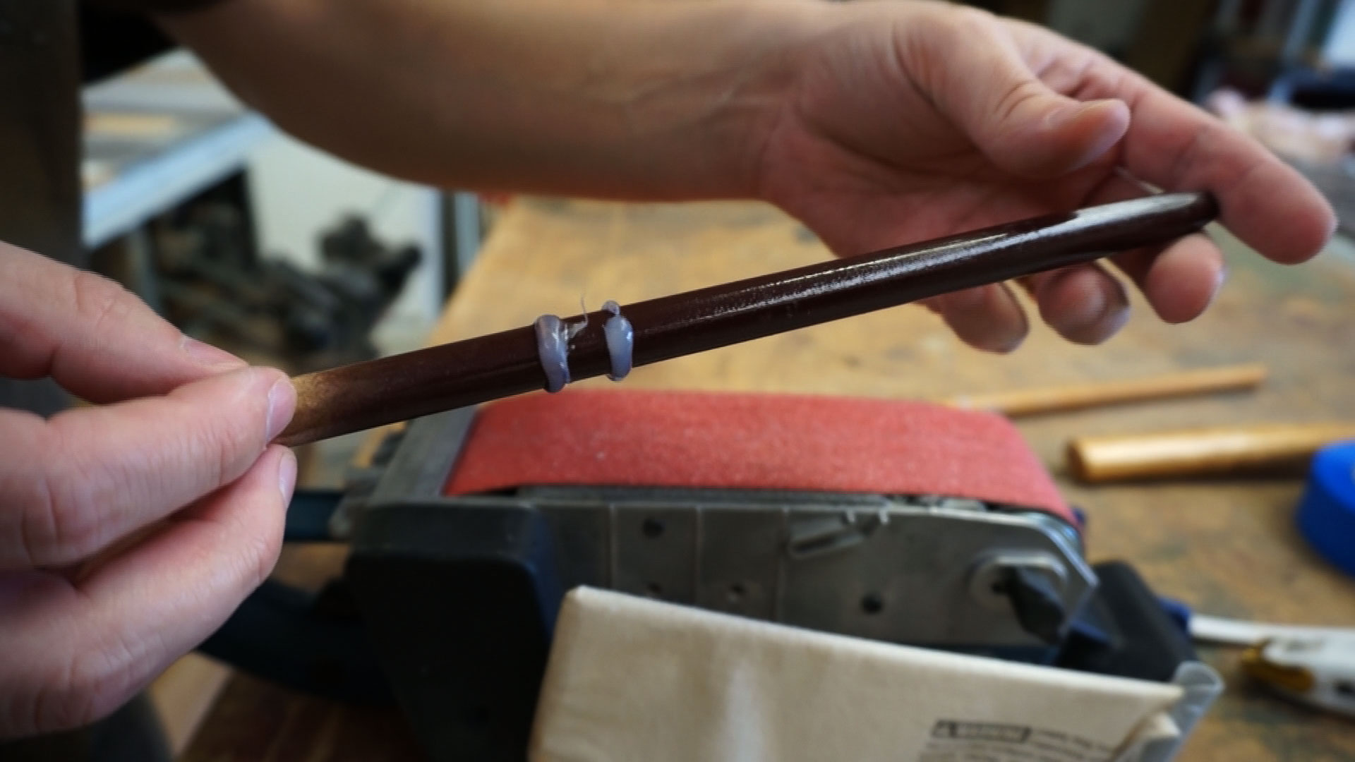
My goal was to apply a consistent bead of glue around the wand in two places to make handle guards. A proper wand done up in a lath would have those bits carved into the wood but in my case, I needed something to add to it. Hot glue was supposed to dry to a decently hard state so I gave it a try.
My procedure was to slowly spin the wand in a groove in a work table, keeping it from going back and forth, while holding the glue gun stationary. I did try some test pieces earlier with a more freehand style and that didn’t work out at all!
As it is, even this method didn’t work out as well as I’d hoped. The problem was that the glue came out in blobs rather than a consistent thickness bead. I don’t know if that’s a property of glue guns or if my inexperienced technique was wrong. The end result looked like this after it dried:
That needed to be fixed in two ways. The diameter of the guards needed to be made consistent to tamp down some of the more egregious blobs of glue and then the thickness of each needed to all be normalized.
I used the belt sander to make the diameter consistent. That was mostly me slowly spinning the wand over the running sander until it looked right. That part was very easy since the sander easily worked through the glue.
Getting the proper thickness was mildly more tedious. I used a utility knife to cut along the side to square them up. That absolutely worked, but the glue sticking to the wand and to itself slowed down the process quite a bit. From a pure time perspective, this step took the longest.
In the end, it looked like this:
Not great, but not bad. My thinking was that it would all be painted black when it was done and so it wouldn’t be very noticeable. Indeed, it’s not.
Finishing Up
The handle is jet black. I didn’t even bother trying some kind of stain or similar and just went directly to the spray paint. I thoroughly taped over the brown parts to not get any overspray. I debated doing a quick clear coat over the tape line to prevent any bleed under. That trick works well if paint bleeding is going to be a problem. In this case, since I was going to be holding the wand so that the painted part is on the bottom and since the tape line was right at a vertical element (the top guard), I didn’t think it was necessary. It wasn’t.
I did three coats of black, like the brown before it and let it dry.
The texture of the painted wand was a little bit rough and so I decided to try sanding it with 320 grit paper to just knock down the texture a bit.
That worked… but I apparently didn’t have as thick a paint layer as I thought since even that very light sanding sanded through the layers in a couple places. It wasn’t a bad look since it has the effect of grain and that had its own appeal… but it was different than intended so I only did one of the wands that way.
The final step was to apply a clear coat. I used a Polycrylic spray since that’s worked well for us in the past. I wanted to spray the entire wand at once, though, so I couldn’t use my normal clamps.
My workaround was the screw in a #6 screw into the tip of the hand and hang it via a think piece of wire. This gave me full access to the entire wand at once, short maybe a millimeter or two at the tip. I did a few coats of clear just like all of the other sprayed layers and let it dry overnight.
I colored in the hole left by the screw using a black Sharpie marker.
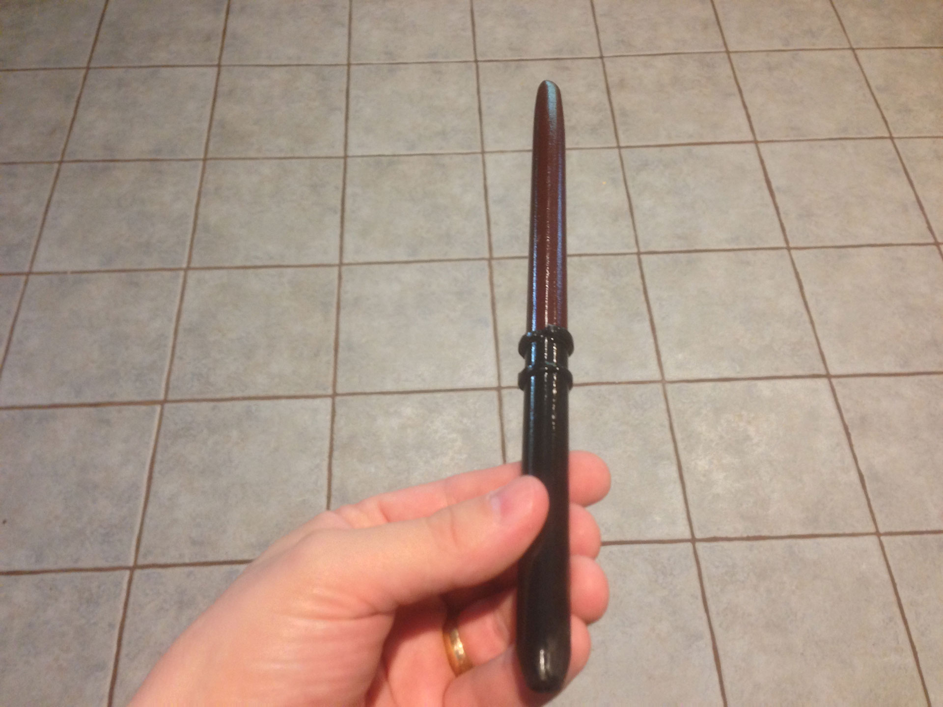
All Done
Here’s what it looks like all finished.
I’m not going to make another one since I already have twice as many as needed… but if I did, I likely would do a few things differently. First, I wouldn’t use hot glue to make the hand guards. Instead, I would experiment with some kind of moldable putty. Maybe just roll it out into a thin bead and then wrap it around the wand and press it in? Or maybe a moldable plastic like Sugru? No matter what, I’d like it to be something that I could work and shape while it’s not super hot.
I’m also going to have to create a better spray booth for future projects. Using that particular room won’t work since it’s too dark in there. I can’t see what kind of painting job I’m doing until I’m done.
Other than that… it’s okay. Simple and our son loves it!


")


")